EPC Technical Specifications
This appendix provides the Endpoint Controller's hardware details: a mechanical drawing, the I/O connector pinout, electrical ratings, safety input and output specifications, and the radio, Wi-Fi, and Ethernet specifications for each EPC model.
EPC Mechanical Drawing
The following figure shows a mechanical drawing of the EPC 1001. Note that all models have the same dimensions.
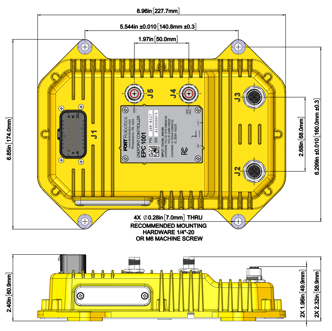
The following table shows the recommended connectors for an Endpoint Controller device.
| Connector # | Suggested Mating Connector Type for EPC |
|---|---|
| J1 | TE 770680-1. |
| J2 |
Ethernet M12 – D Type for management port connection. Connect to a port on a Linux or Windows machine to update firmware or load a configuration to the EPC. |
| J3 | Ethernet M12 – D Type for connection to safety network. |
| J4 | RP-TNC Plug (male) with center socket (female) quick disconnect antenna port for 2.4 GHz BLE & Wi-Fi antenna. |
| J5 | RP-TNC Plug (male) with center socket (female) quick disconnect antenna port for 8xx and 9xx ISM antenna. |
Connectors are designed to be hand tightened only. Use of a wrench or other tool will cause damage to the connector or cabling. The EPC has no user-serviceable parts. Do not attempt to open the device nor make any changes or repairs. If you have maintenance or repair questions email support@fortrobotics.com.
EPC I/O Connector Pinout and Cable
The following figure shows a diagram of the EPC’s 23 pin I/O connector (the J1 connector on the Endpoint Controller).
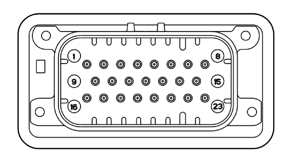
The suggested mating connector to this port is a TE 770680-1 and the cable is the FORT #100-0256 Integration Cable.
The following table describes each of the connector signals. Refer to the diagram and table when wiring devices to an Endpoint Controller sender (Wiring EPC Sender) or receiver (Wiring EPC Receivers).
| Pin # | Name | Description | Wire Color FORT integration |
|---|---|---|---|
| 1 | IN5_CONN | Channel 1, Input 3 | White |
| 2 | IN4_CONN | Channel 1, Input 2 | White |
| 3 | IN3_CONN | Channel 1, Input 1 | White |
| 4 | IN2_CONN | Channel 0, Input 3 | White |
| 5 | IN1_CONN | Channel 0, Input 2 | White |
| 6 | IN0_CONN | Channel 0, Input 1 | White |
| 7 | PVin_RTN | Voltage Negative Polarity | White |
| 8 | PVin_RTN | Voltage Negative Polarity | White |
| 9 | CH_GND |
Chassis to Ground Connection; Connect to power supply common if an earth ground is not available (such as in a moving vehicle). See Grounding an EPC for details. |
White |
| 10 | Reserved | Do not connect | |
| 11 | CAN1_L | CAN Low, Twisted with 12 | Green |
| 12 | CAN1_H | CAN Hi, Twisted with 11 | Yellow |
| 13 | CAN1_SHIELD | CAN Bus Shielding; See CAN Interface if you require shielding for CAN. | |
| 14 | PVin_IN | Voltage Positive Polarity | White |
| 15 | PVin_IN | Voltage Positive Polarity | White |
| 16 | OUT5_CONN | Channel 1, Output 3 | White |
| 17 | OUT4_CONN | Channel 1, Output 2 | White |
| 18 | OUT3_CONN | Channel 1, Output 1 | White |
| 19 | Reserved | Do not connect | |
| 20 | Reserved | Do not connect | |
| 21 | OUT2_CONN | Channel 0, Output 3 | White |
| 22 | OUT1_CONN | Channel 0, Output 2 | White |
| 23 | OUT0_CONN | Channel 0, Output 1 | White |
The outputs in the table above are dual channel pairs — each output uses one pin from Channel 0 and one from Channel 1:
-
Output 1 — pins 23 (Channel 0) and 18 (Channel 1)
Output 2 — pins 22 (Channel 0) and 17 (Channel 1)
Output 3 — pins 21 (Channel 0) and 16 (Channel 1)
In a configuration with an Output to Control setting, that setting determines which pair carries the safety signal. For more information, see Choosing Which Output the Senders Control.
We highly recommend ordering and using the FORT supplied integration cable (#100-0256). Consult with customer support before using a custom cable.
Recommended and Absolute Maximum Ratings (EPC)
The following table shows the recommended and absolute maximum ratings for the Endpoint Controller.
| Specification | Minimum | Typical | Maximum |
|---|---|---|---|
| PVin (12V operation) | 9.6 | 12 | 14.4 |
| PVin (24V operation) | 19.2 | 24 | 28.8 |
| PVin (V) | 8 | 32 | |
| Input Voltage | 0 V | Vin+0.7 V | |
| Current (not including output loads) | 87 mA @32V | 273 mA @8 V | |
| Weight | 878 g | 1.9lb | ||
| Ingress Protection | IP65 | ||
| Dimensions |
228 mm x 176 mm x 70 mm 6.85” x 8.99” x 2.40” |
||
| Operating and Storage Temperature | -40 °C | 85 °C | |
| Connectors |
M12 Ethernet connectors (2); 23-pin main integration connector; RP-TNC antenna connectors (1 for BLE models, 2 for ISM models) |
||
| Certification | SIL 3 Certified per IEC 61508 |
Safety Input Specifications
The following table provides specifications for the safety inputs:
| Specification | Minimum | Typical | Maximum |
|---|---|---|---|
| Safety Inputs | Three dual channel inputs | ||
| Input Voltage | 0 V | Vin+0.7 V | |
| Input Current | 5.75 mA @8 V | 51.35 mA @32 V | |
| Normal State Input | 8 | 32 | |
| Safe State Input | Open Circuit/Hi-Z | ||
| Input state for logic ON/HIGH | 8VDC | 12VDC (or 24VDC) | 32VDC |
| Input state for logic OFF/LOW | 0VDC | 0 ~ 1VDC | Less Than 8VDC |
| Input Impedance | TBD |
Safety Output Specifications EPC
The following table provides specifications for the safety outputs:
| Specification | Minimum | Typical | Maximum |
|---|---|---|---|
| PVin (12V operation) | 9.6 | 12 | 14.4 |
| Output ON State | 9.6V | 12 | 14.4 |
| On-state Voltage Drop | 1.057 V | ||
| PVin (24V operation) | 19.2 | 24 | 28.8 |
| Output ON State | 9.6V | 24V | 28.8 |
| Safety Outputs | Three dual channel outputs | ||
| Output safe state (logic OFF/LOW) | 0 V | 0V | 0V |
| Output Type | Current Sourcing | ||
| Current (per output channel) | 750 mA | ||
| Leakage Current (OFF state) | 0.714 uA @8 V | 0.892 uA @32 V | |
| OSSD Pulse Width | 300 μS | ||
| OSSD Pulse Period | 200 mS |
Wireless Radio Specifications (EPC)
You can purchase an Endpoint Controller with any of several different radios based on frequency requirements and local regulations. Prior to ordering and deployment, consult local regulations to ensure that you are obtaining an EPC with the proper radio.
North America ISM Radio (EPC)
The following table provides the specifications for North America ISM radio 902-928 MHz:
| Specification | Minimum | Typical | Maximum |
|---|---|---|---|
| Frequency | 902 MHz | 928 MHz | |
| Bandwidth | 600 kHz | ||
| Channels | 21 | 21 | |
| Receive Sensitivity | -100 dBm | ||
| Modulation | 2-GFSK | ||
| Baud Rate | 500 kbps | ||
| Power (conducted RF output) | -10 dBm | 23 dBm | |
| EPC Part # | North America ISM radio is available in EPC model 1001 |
European ISM Radio (EPC)
The following table provides specifications for the European ISM radio:
| Specification | Minimum | Typical | Maximum |
|---|---|---|---|
| Frequency | 869.4 MHz | 869.653 MHz | |
| Bandwidth | 250 kHz | ||
| Channels | 1 | ||
| Receive Sensitivity | -100 dBm | ||
| Modulation | 2-GFSK | ||
| Baud Rate | 200 kbps | ||
| Power (conducted RF output) | -10 dBm | 23 dBm | |
| EPC Part # | EU ISM radio is available in EPC model 1002 |
Bluetooth Low Energy (BLE) Radio (EPC)
The following table provides specifications for the BLE radio:
| Specification | Minimum | Typical | Maximum |
|---|---|---|---|
| BLE Version | 5.1 | ||
| Baud Rate | 1 Mbps | ||
| Power (conducted RF output) | 4 dBm | ||
| Receive Sensitivity | -99 dBm | ||
| EPC Part # | EPC-1000, EPC-1001, EPC 1002 |
The following table provides specifications for the Long-Range Bluetooth (LRBLE) radio, which is carried by the EPC1003 model only:
| Specification | Description |
|---|---|
| BLE Long Range Version | 5.0 |
| Tx Power (conducted RF output) | 17 dBm |
| Receive Sensitivity | -105 dBm |
| Range | 100-300 m |
| EPC Part # | EPC 1003 |
Wi-Fi Specifications
The EPC supports 2.4 GHz and 5 GHz Wi-Fi (access point is not included). The following table provides specifications:
| Specification | Description |
|---|---|
| Max Power | 20 dBm |
| Range | ~50 m (customer coverage dependent) |
Ethernet Specifications
The following table provides Ethernet specifications:
| Specifications | Minimum | Typical | Maximum |
|---|---|---|---|
| Speed | 10/100 Mbps |
Data Interfaces
The Endpoint Controller’s integration interface is USB or CAN (Controller Area Network). “CANopen Implementation” on page 6-1 describes CAN communication specifications (data rates and protocol). Use the Endpoint Controller’s dual safety outputs to prevent any motion of the equipment under control (EUC) when the Endpoint Controller receives an emergency stop from either the connected remote device or its wired emergency stop input. The emergency stop inputs are relative to PVin. Maintain a single ground reference for all power and reference voltages.
The following table provides specifications for the CAN interface.
| Specification | Minimum | Typical | Maximum |
|---|---|---|---|
| Common Mode Voltage | -30V | 30 V | |
| Positive Going Input | 900 mV | ||
| Negative Going Input | 500 mV | ||
| Diff Input Resistance | 30 k | 80 k | |
| Single Input Resistance | 15 k | 40k | |
| Driver output current | -100 mA | ||
| during short-circuit conditions | 100 mA | ||
| during short-circuit conditions | |||
| Driver input current | -4 mA | 4 mA |