Recommended Relays
This appendix lists the safety relays and diodes that FORT has tested with EPC and NSC Pro receivers, and provides a wiring diagram for each one to get you started.
This appendix describes the relays that we have tested for use with an EPC or NSC Pro receiver:
EPC Recommended Relays
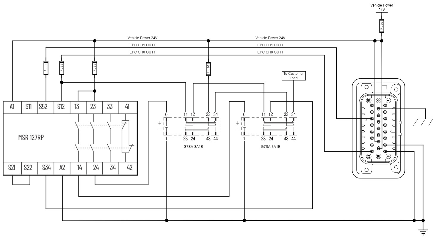
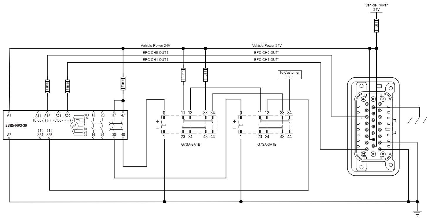
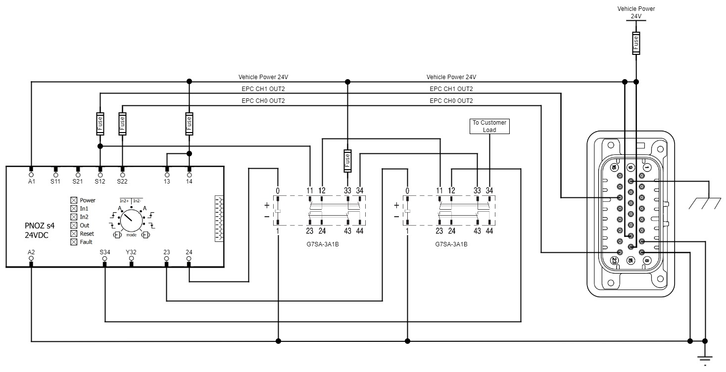
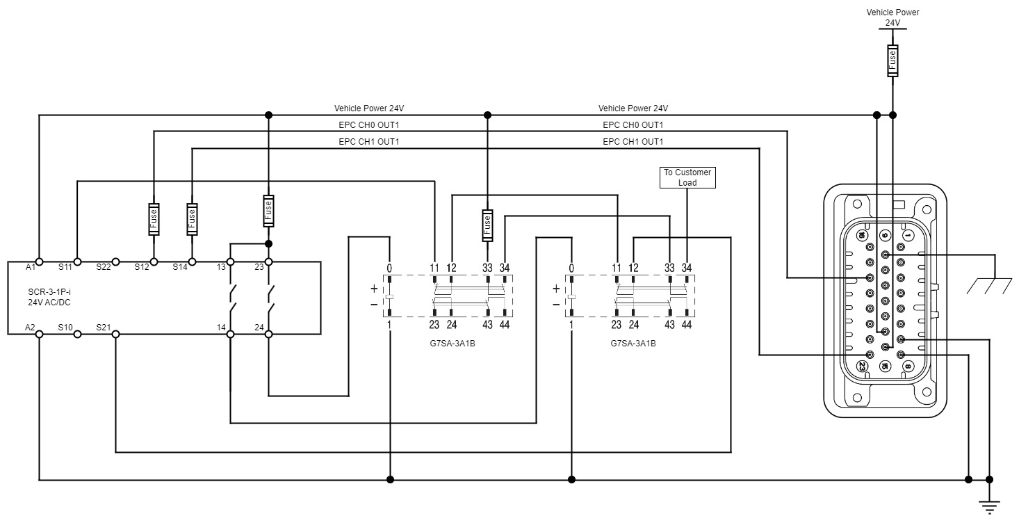
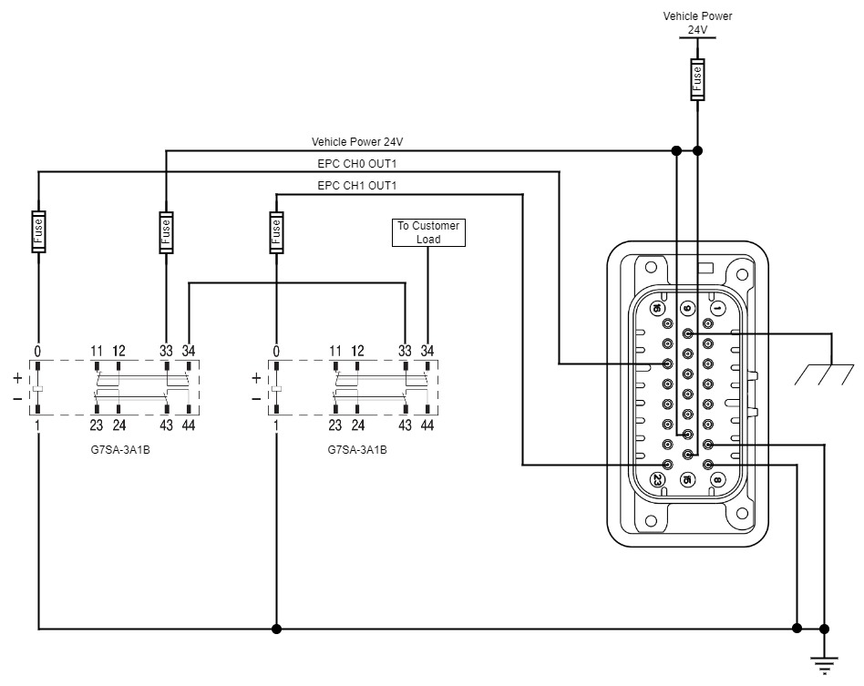
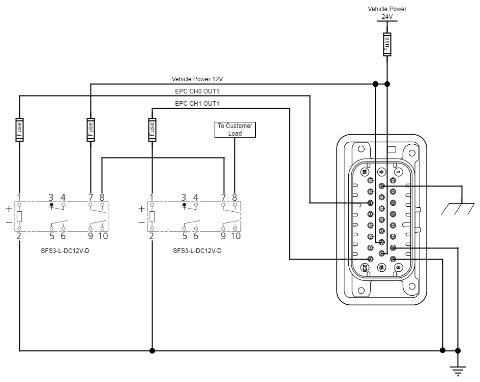
The sections that follow provide a wiring diagram for each relay that we have tested for use with an EPC receiver.
These wiring guides are intended as a quick start to assist you in wiring your FORT devices to your equipment, but are in no way a definitive guide to any of the relays. Be certain to consult the manufacturer’s documentation for whichever relays you are using.
To satisfy applicable wiring codes and conditions, you are responsible for protection of field devices and wiring through appropriate fusing of the circuitry. You can fuse the EPC circuit in a number of different ways, but to determine the size of the fuse(s) you must account for:
-
The EPC current, which is 87 mA@ 32V or 273 mA@ 8V (from the table in Recommended and Absolute Maximum Ratings (EPC)).
-
The current per output channel (which you must measure as it varies based on your setup).
-
The relay current (which you must measure as it varies based on your setup).
When testing your system, and before putting it into production, be certain to measure your actual current.
You must provide a flyback diode (external or built-in to the relay) to prevent reverse voltage (flyback) when the relay coils shutoff in response to a safety signal. The forward voltage of the diode should be standard (0.7 V), but the reverse breakdown voltage of the diode must be greater than the expected system voltage that will drive the relay coil. This diode should conduct in its forward-biased condition only (which occurs when the coil is suddenly de-energized in the case of the safety outputs of the system going from high to low).
The EPC utilizes OSSD test pulses to detect shorts, so the downstream safety input must be able to filter out these pulses (all of the recommended relays meet this criteria). Be sure that any chosen relay is compatible with these pulses and meets any other safety or reliability requirements of the application.
See OSSD Pulses for detailed information on how Pro series receivers use OSSD pulses, including how to turn them off for NSC Pro devices.
| Manufacturer | Model | Supply Voltage | Link to Wiring |
|---|---|---|---|
| Allen-Bradley | MSR127TP | 24V | Allen-Bradley MSR127TP |
| EATON | ESR5-NV3-30 | 24V | EATON ESR5-NV3-30 |
| PILZ | 751104 | 24V | PILZ 751104 |
| IDEM | SCR-3-1P-i | 24V | IDEM SCR-3-1P-I |
| OMRON | G7SA-3A1B | 24V | OMRON G7SA-3A1B |
| PANASONIC | SFS3-L-DC12V-D | 12V | PANASONIC SFS3-L-DC12V-D |
Allen-Bradley MSR127TP
EATON ESR5-NV3-30
PILZ 751104
IDEM SCR-3-1P-I
OMRON G7SA-3A1B
PANASONIC SFS3-L-DC12V-D
NSC Pro Recommended Relays
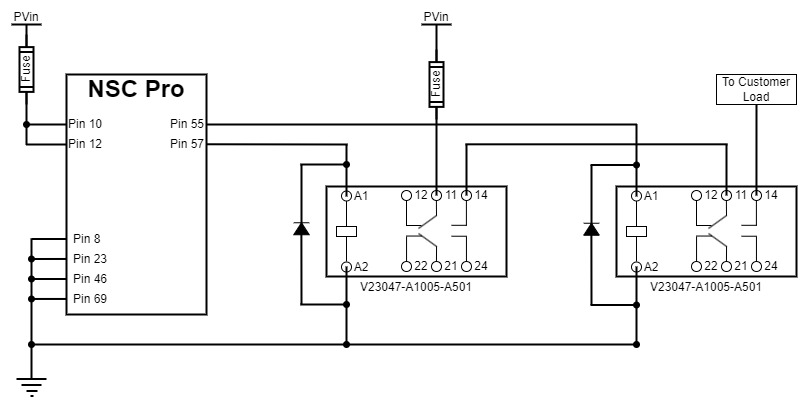
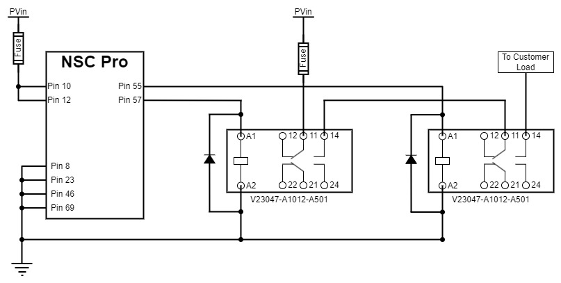
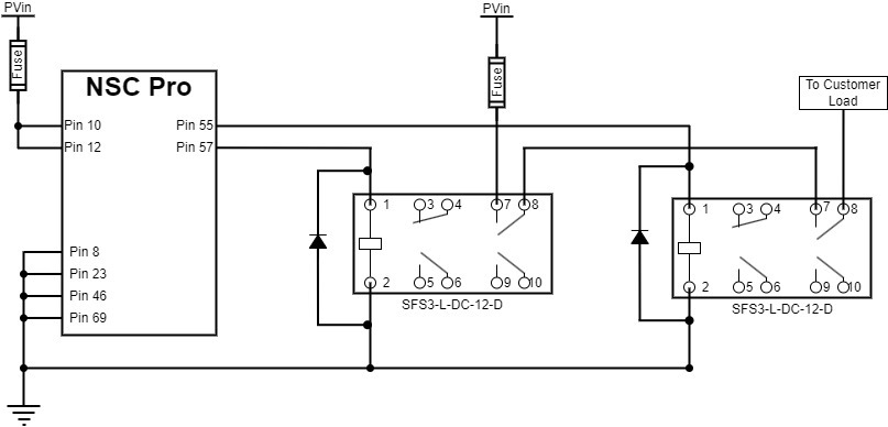
The sections that follow provide a wiring diagram for each relay that we have tested for use with an NSC Pro.
These wiring guides are intended as a quick start to assist you in wiring FORT devices to your equipment, but are in no way a definitive guide to any of the relays. Be certain to consult the manufacturer’s documentation for whichever relays you are using.
To satisfy applicable wiring codes and conditions, you are responsible for protection of field devices and wiring through appropriate fusing of the circuitry. As a rule of thumb, calculate fuse size on PVin as:
(pvin_current+output-driving-current(perchannel)+relay_current)x1.5The table in Recommended Operating Conditions shows the current and driving current as:
-
current: 80 mA (serial comms) or 650 mA (ISM max power)
-
driving current per channel: 230 mA.
When testing your system, and before putting it into production, be certain to measure your actual current.
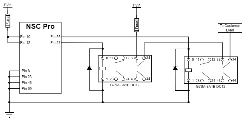
To ensure reliable operation, you must connect a Schottky diode in reverse bias across the relay coil terminals. The following table shows the diodes that we recommend.
| Manufacturer | Part # |
|---|---|
| Onsemi | NRVB130LSFT1G |
| Various | 1N5822 |
The NSC Pro utilizes OSSD test pulses to detect shorts, so the downstream safety input must be able to filter out these pulses (all of the recommended relays meet this criteria). Be sure that any chosen relay is compatible with these pulses and meets any other safety or reliability requirements of the application.
See OSSD Pulses for detailed information on how Pro series receivers use OSSD pulses, including how to turn them off for NSC Pro devices.
| Manufacturer | Model | Supply Voltage |
|---|---|---|
| TE | V23047-A1005-A501 | 5 |
| TE | V23047-A1012-A501 | 12 |
| PANASONIC | SFS3-L-DC12V-D | 12V |
| OMRON | G7SA-3A1B DC12 | 12 |
For each of the following relays, be certain to consult the manufacturer’s documentation for proper installation instructions, including what size fuse to attach to the relay contactors.
 1